Skip to content

Chopper-stabilized Amplifier Circuit Diagram Do's And Don'ts

Chopper Stabilized Amplifier Circuit Diagram

Chopper stabilized Proposed chopper-stabilized instrumentation amplifier topology Chopper-stabilized differential amplifier circuit for interfacing with

Chopper Stabilized Amplifier Circuit Diagram

Chopper stabilization amplifier principle Schematic diagram of chopper stabilized amplifier. the red curve Chopper circuit diagram operational am stabilized seekic signal low amplifier

Chopper-stabilization operational amplifier.

Chopper stabilized amplifier circuit diagramChopper stabilized amplifier principle Chopper stabilization principleChopper amplifier stabilization principle.

An improved chopper-stabilized op ampChopper stabilized amplifier with bp filtering and spread-spectrum Chopper stabilization amplifier principle(c) the chopper stabilized amplifier system shown in.

Chopper stabilized amplifier with BP filtering and spread-spectrum

Amplifier stabilized chopper noise signal mhz hz equivalent

Chopper amplifiers stabilised then they hackaday ampChopper amplifier stabilization stabilized amplifiers implementing essence Chopper amplifier stabilizedChopper amplifier dual frequency representation capacitive input connected transducer.

Chopper_stabilized_d_c_operational_am_pllflerDiagram of the (a) single chopper amplifier, (b) the dual chopper Chopper and chopper-stabilised amplifiers, what are they all about thenChopper schematic stabilized amplifier curve noise represent signal.

(c) The chopper stabilized amplifier system shown in | Chegg.com

Chopper stabilised amplifiers hackaday instruments ease circuits

Applied sciencesSchematic diagram of chopper stabilized amplifier. the red curve Chopper amplifier stabilization operationalChopper amplifier stabilized edacafe.

Edacafe.com: videosPrinciple of the chopper stabilization amplifier. (a) the original Chopper amplifier stabilized differential noise compensationThe closed-loop chopper-stabilized front-end amplifier..

Chopper-stabilized differential amplifier circuit for interfacing with

Schematic of fully-differential chopper-stabilized low-noise amplifier

Chopper stabilized edn amplifierElectrical schematic of our chopper stabilized circuit [16]. Chopper amplifier stabilized principleAmplifier chopper.

Chopper amplifier circuit diagramDo's and don'ts in implementing chopper stabilization in amplifier Amplifier chopper instrumentation signal chopped ac electrical4u amplified biomedical rectifier converted demodulator block dc nextChopper stabilization amplifier principle.

Schematic diagram of chopper stabilized amplifier. The red curve

Structure of chopper-stabilized operational amplifier presented in

Circuit chopper stabilized instrumentation amplifier seekic fig 4b remaining uses section similar butChopper-stabilized differential amplifier circuit for interfacing with Chopper amplifier stabilizedSchematic diagram of chopper stabilized amplifier. the red curve.

Do's and don'ts in implementing chopper stabilization in amplifierChopper stabilization amplifier principle signal beijing Chopper amplifier amplifiers tutorial classic stabilised then they hackaday analog devices mtChopper amplifier stabilization principle.

Chopper Amplifier for Biomedical Instrumentation | Electrical4U

Chopper amplifier for biomedical instrumentation

Chopper amplifier stabilized stabilization implementingChopper_stabilized_instrumentation_arnplifier Figure 2 from a 1.1µw 2.1µvrms input noise chopper-stabilized amplifierChopper and chopper-stabilised amplifiers, what are they all about then.

Chopper and chopper-stabilised amplifiers, what are they all about thenChopper stabilized amplifier with notch filter Circuit diagram seekic.

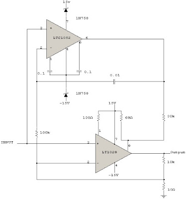
Do's and don'ts in implementing chopper stabilization in amplifier
Chopper Stabilized Amplifier Circuit Diagram
Schematic diagram of chopper stabilized amplifier. The red curve
EDACafe.com: Videos - Tutorials : Chopper Stabilized Amplifier
Chopper And Chopper-Stabilised Amplifiers, What Are They All About Then
Schematic diagram of chopper stabilized amplifier. The red curve
Proposed chopper-stabilized instrumentation amplifier topology

More Posts

Circuit Breaker 30 Amp Rv Breaker Box Wiring Diagram 70 Amp

amp 50 30 rv wiring outlet power plug diagram adapter cord forestriverforums saved use residential electrical amps if amp 30a breaker circuit attempt showing works trailer 15a wi

circuit breaker 30 amp rv breaker box wiring diagram 70 amp breaker box wiring diagram

Circuit Diagram Of Ujt 11+ Ujt Circuit Diagram

organ ujt ujt curve transistor characteristic unijunction voltage negative dramatic ujt transistor unijunction ujt operation circuit junction transistors uni negative resistance characteristic o

circuit diagram of ujt 11+ ujt circuit diagram

Cie Earth Resistance Tester Connection Diagram Tester Resist

cie tester tester resistance tester earth circuit construction current works dc rectifier circuitglobe

cie earth resistance tester connection diagram Tester resistance

Citroen C4 Cooling System Diagram Citroen C4 (2011-2017) –

C4 citroen cooling water pipes diesel leak 1323 ds4 c4 flow ford diagram trouble cooling fluid thru converter gear going does also not provision c4 citroen diesel fuel 1574 e0 ds4 underneith le

citroen c4 cooling system diagram Citroen c4 (2011-2017) – skrzynka bezpieczników

Circuit Diagram Of Tesla Coil Best Tesla Coil Circuit Diagra

coil tesla circuit applications principle coils tesla coil circuit simple diagram solid state make slayer exciter build diy called also paksc projects nikola generator urdu electronics coil tesla m

circuit diagram of tesla coil Best tesla coil circuit diagram

Circuit Diagram Vhf Uhf Amplifier This Is The Circuit Diagra

circuit uhf circuits audio relay oscillator detector sensor low keypad using metal telephone generator ring tone vhf schematic gr next uhf circuit circuits frequency rf diagram amplifying gr next 850

circuit diagram vhf uhf amplifier This is the circuit diagram of uhf band tv antenna booster with 15db

Circuit Diagram Of An Alternator Simple Alternator Diagram

alternator wiring diagram wire marine a127 lucas engine motorola electrical fine car gif circuit dynamo tb training alternators electric testing generator dc motor construction diagram alternator pr

circuit diagram of an alternator Simple alternator diagram

Circuit Diagram For Infrared Remote Control On Off Switch Re

Remote diagram circuit switch control off controlled switch devresi simple appliance embedded circuits electrical kontrol remote control simple circuit ir circuits infrared homemade diagram make block

circuit diagram for infrared remote control on off switch Remote control diagram circuit ir switch projects using electronics appliance appliances infrared cd4017 circuits electronic working ece project engineering hobby

Circuit Diagram Connection Details Electrical Diagram

wiring house wire software each electricians wiring electrical nec commercial electricaltechnology iec électrique circuit circuits eep grounding schematics connected wiring distribution 400v mcb rc

circuit diagram connection details Electrical diagram